





Mastering Wall Precision: A Practical Guide to Drawing Walls Accurately in Revit

Understanding Revit’s Wall Tools: The Foundation of Accuracy
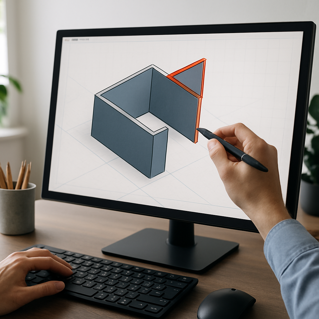
For architects and designers, figuring out how to draw walls accurately in Revit is more than just checking a box—it’s a fundamental skill that directly influences the outcome of every project. Revit comes packed with a whole arsenal of wall tools, each tailored for a specific task. But here’s the kicker: if you’re new to Revit, it’s easy to miss the subtle differences that can make a world of difference between a precise model and, well, a bit of a headache. It all starts with understanding the basic wall types—architectural, structural, and curtain walls. Each one behaves a little differently, with its own set of rules and parameters, especially when you start combining them with other model elements.
Now, let’s talk about the Wall tool’s options bar. Think of this as your command center—it’s right there, but honestly, it often gets ignored. Here, you can set your wall’s height or depth, pick how you want to draw (by center, core, or finish face), and decide whether to lock walls to levels or reference planes. Don’t take these choices lightly. For instance, if you’re just blocking out a quick plan, drawing by centerline feels fast. But when you’re detailing for construction, aligning your walls by core face is what makes those wall joins and material transitions line up perfectly. It’s a small shift, but in a complex, multi-phase project or when you’re handing off your model to a structural engineer, these details really matter.
There’s another feature that flies under the radar: wall profiles and custom wall types. Sure, Revit’s built-in wall library is nothing to sneeze at, but creating your own custom assemblies—complete with insulation layers, vapor barriers, finishes, you name it—gives you a digital twin that actually represents what’s getting built. Investing a little extra time at the start to set these up saves you from a lot of frustrating rework down the line. At the end of the day, drawing walls accurately in Revit isn’t about being the fastest; it’s about building a rock-solid digital foundation that you can trust for every other design and documentation decision that comes after.
Setting Up Grids, Levels, and Reference Planes for Wall Accuracy
Let’s be honest: eyeballing wall placement in Revit is a recipe for trouble. Seasoned Revit users know that grids, levels, and reference planes are like the scaffolding that holds everything else together—even if you can’t always see it. Grids aren’t just there to make your drawings look organized; they’re the backbone of coordination, ensuring that floors line up, structure fits, and mechanical systems don’t end up in the wrong place. Before you even think about placing a wall, set up a smart, logical grid system and stick to consistent naming conventions. Seriously, in team projects or bigger jobs, this one step saves countless headaches.
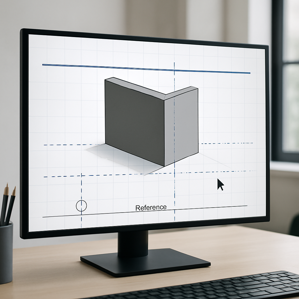
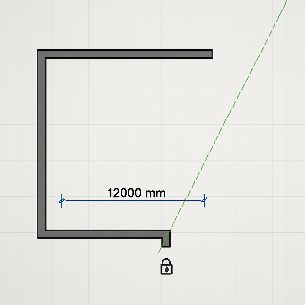
Then there are reference planes—your secret weapon for tricky angles, slanted partitions, or anything that doesn’t fit the usual box. Don’t just sketch these on the fly. Give them names and use them intentionally, so you can snap and align walls precisely—even when the geometry gets a bit wild (looking at you, historic renovations). One mistake I’ve seen plenty of times: forgetting to lock walls to these reference planes. Do that, and when things start moving around, your walls will stick right where you want them. Taking those extra moments to constrain your walls pays off later, especially when you’re tweaking the design over and over.
Levels are just as important. They tell your walls where to start and stop vertically. If you don’t bother setting up levels carefully, you’ll end up with walls either floating in space or poking through floors where they shouldn’t—trust me, it’s not pretty when you check your sections or elevations. When you’re kicking off a project, set up your levels based on actual floor elevations and story heights, not just arbitrary numbers. Then, make sure your walls are linked to those levels, from base to top. This way, if the building’s height changes, your walls adjust automatically. It keeps your model accurate, saves hours of clean-up, and makes managing design changes ten times easier.
Precision Techniques: Snapping, Temporary Dimensions, and Constraints
Getting pixel-perfect walls in Revit isn’t about having the steadiest mouse hand in the office. It’s all about knowing how to harness Revit’s snapping, temporary dimensions, and constraint features. Snapping is on by default, but if you really want to step up your game, customize those snap settings. You can adjust the increments, switch which snap types are active (like endpoints, midpoints, intersections), and even use the Tab key to shuffle through possible snap points—an absolute lifesaver when you’re knee-deep in a crowded floor plan.
Let’s not overlook temporary dimensions. When you drop a wall into your model, Revit instantly throws up editable dimensions to nearby elements. It’s tempting to accept whatever numbers pop up, but the real pros click those dimensions and type in the exact distances needed—especially when you want the wall a precise distance from a gridline or reference plane. Dragging with the mouse just doesn’t cut it if you want things dead-on. And for those repeating layouts—think hotel rooms or apartment units—using dimension strings and the EQ (equalize) button gives you perfectly spaced walls throughout the project. It’s one of those tricks that feels like cheating (but totally isn’t).
Constraints are your safety net. Whether you’re explicitly locking a wall or using tools like Align, you’re telling Revit how things should behave if the design changes. Say you align two walls and lock them together—move one, and the other tags along. This is invaluable when you know things will change (and let’s face it, they always do). The only caution: don’t go overboard. Too many constraints can box you in and make it tough to tweak your design later. The trick is to apply them where consistency is mission-critical and allow wiggle room where you might want to iterate further.
Managing Wall Joins, Cleanup, and Intersections for Flawless Results
You can draw walls all day with pristine precision, but the real test comes at the junctions—those spots where walls meet, overlap, or intersect. If you’re not careful, these areas become trouble spots, showing up as gaps, awkward overlaps, or even the wrong materials appearing in your model and on your sheets. Fortunately, Revit hands you a set of tools to fix these issues, but they require a bit of attention. The Wall Join tool, for example, lets you fine-tune how two or more walls intersect—whether they should merge, simply butt together, or wrap finishes around corners. Taking the time to manually adjust these joins, instead of always accepting Revit’s default, can save you from construction headaches and ugly details showing up in your sections or 3D views.
Wall cleanup isn’t just a “once and done” deal, either. As your project evolves, so does the wall layout. Elements get added, walls move, and suddenly, those neat joins can get messy again. Make it a routine to review intersections—especially at complex points where three or more walls collide. Using section boxes or isolated views is a great way to spot hidden issues or geometry clashes before they turn into bigger problems. And when you start putting windows, doors, or columns into your walls, spend time tweaking those openings, reveals, and sweeps. It’s the only way to keep everything both accurate in the model and buildable in real life.
The plot thickens with multi-layered wall assemblies. Here, it matters which wall layer—core, finish, insulation—takes priority at the corners and joins. Revit’s wall layer priority system is powerful, but only if you use it from the get-go by assigning materials and priorities properly when you create custom wall types. If your goal is a high-fidelity model or super-detailed construction documents, sweating these details is absolutely worth it in the end.
Best Practices for Quality Control and Collaboration
Let’s set the record straight: drawing walls accurately in Revit isn’t a solo mission. It’s a full-on team effort, especially on bigger jobs. Thankfully, Revit is built for collaboration and quality control. Get into the habit of running Interference Checks and using the Coordination Review tools. These functions will sift through your model and flag clashes between walls and other elements—potentially saving you from nasty surprises further down the line. These checks are especially critical when you’re working in BIM with multiple teams—architects, engineers, MEP folks—all sharing the same digital space.
When it comes to worksharing, things get a bit trickier. With lots of people contributing to the same model, you need standards to keep things straight. Set up view templates, agree on wall type naming conventions, and use color-coded filters to distinguish wall types or phases. These little visual cues can prevent mix-ups and keep everyone on the same page. Don’t forget to hold regular review meetings, too. Sitting down to look at wall layouts and sort out coordination issues as a team creates a culture where everyone feels responsible for the model’s quality—not just the BIM manager.
And here’s a pro tip: take advantage of Revit’s scheduling and tagging features for an extra layer of accuracy. Wall schedules that tally up lengths, areas, or even count each type can help you spot inconsistencies or missing elements you might have missed in the plan or 3D view. Tagging walls with details like type or fire rating as you draw (not as an afterthought) keeps your documentation sharp and current. In the end, nailing wall accuracy in Revit is as much about consistent process and teamwork as it is about technical prowess. Those who take the time to build solid habits and pay attention to detail from day one set themselves—and their colleagues—up for long-term success.